Control Circuit
Solid_state_time_delay
Published:2009/7/22 3:48:00 Author:Jessie | From:SeekIC

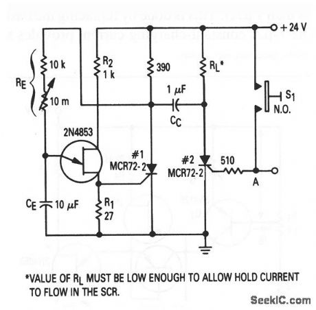
This circuit shows the basic UJT building block (Fig. 9-1), which is used to provide a time-delay function. The circuit is similar to that of Fig. 9-13, except that the mechanical relay is replaced by an SCR (which generally reduces circuit cost). When S1 is pushed, or when a positive-going pulse is applied at point A, SCR#2 turns on and SCR#1 is turned off by CC. With SCR#1 off, the supply voltage is applied to RE, and the circuit begins to time. After a period (determined by the setting of RE), the UJT fires and turns SCR#1 on and SCR#2 off. With the values shown, time delay can be varied from about 1 s to over 2 min.
Reprinted Url Of This Article:
http://www.seekic.com/circuit_diagram/Control_Circuit/Solid_state_time_delay.html
Print this Page | Comments | Reading(3)

Article Categories
power supply circuit
Amplifier Circuit
Basic Circuit
LED and Light Circuit
Sensor Circuit
Signal Processing
Electrical Equipment Circuit
Control Circuit
Remote Control Circuit
A/D-D/A Converter Circuit
Audio Circuit
Measuring and Test Circuit
Communication Circuit
Computer-Related Circuit
555 Circuit
Automotive Circuit
Repairing Circuit
Code: