Control Circuit
Scintillation Caution Light (4)
Published:2011/6/3 5:35:00 Author:Sue | Keyword: Scintillation, Caution, Light | From:SeekIC

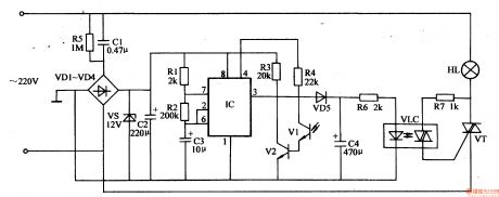
When the oscillator begins to work, IC's 3 pin outputs 1 Hz low frequency square form wave signals. When the signal is positive, VD5 is connected and VLC's LED is illuminated. VT is connected and HL is illuminated.
When the signal is negative, VD5 is disconnected. VLC's LED has a weaker light and HL's light becomes weaker.
Before HL goes out, another positive signal comes and it is illuminated again.
In the daytime, V2 is connected and IC's 4 pin has a low level. VLC and VT are disconnected. HL is not illuminated.
At night, VI has a high resistance value and IC begins to work.
Reprinted Url Of This Article:
http://www.seekic.com/circuit_diagram/Control_Circuit/Scintillation_Caution_Light_4.html
Print this Page | Comments | Reading(3)

Article Categories
power supply circuit
Amplifier Circuit
Basic Circuit
LED and Light Circuit
Sensor Circuit
Signal Processing
Electrical Equipment Circuit
Control Circuit
Remote Control Circuit
A/D-D/A Converter Circuit
Audio Circuit
Measuring and Test Circuit
Communication Circuit
Computer-Related Circuit
555 Circuit
Automotive Circuit
Repairing Circuit
Code: