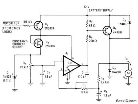
Control Circuit
SWITCHING_MODE_CONTROLLER
Published:2009/7/6 23:49:00 Author:May | From:SeekIC

Developed for driving 0.0l-hp motor M at variable speeds with minimum battery drain. Circuit uses pulses with low duty cycle to set up continuous current in motor approximating almost 200 mA when average battery drain is 100 mA for output volt-age of 3.5 V. Voltage comparator A, serves as oscillator and as duty-cycle element of controller. C1 and R1 provide positive feedback giving oscillation at about 20 kHz, with duty-cycle range of 10% to 70% controlled by feedback loop Q1-R1-C3-R3. D2 is used in place of costly large capacitor for filtering.-J. C. Sinnett, Switching-Mode Controller Boosts DC Motor Efficiency, Electronics, May 25, 1978, p 132.
Reprinted Url Of This Article:
http://www.seekic.com/circuit_diagram/Control_Circuit/SWITCHING_MODE_CONTROLLER.html
Print this Page | Comments | Reading(3)

Article Categories
power supply circuit
Amplifier Circuit
Basic Circuit
LED and Light Circuit
Sensor Circuit
Signal Processing
Electrical Equipment Circuit
Control Circuit
Remote Control Circuit
A/D-D/A Converter Circuit
Audio Circuit
Measuring and Test Circuit
Communication Circuit
Computer-Related Circuit
555 Circuit
Automotive Circuit
Repairing Circuit
Code: