Control Circuit
SONAR_TRANSDUCER_SWITCH
Published:2009/7/9 0:42:00 Author:May | From:SeekIC

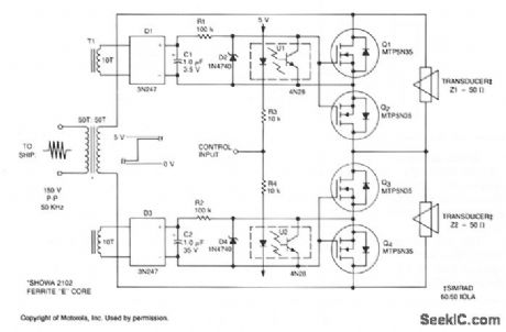
This submersible sonar positioning apparatus generally consists of dual-opposed ultrasonic transducers, alternately excited, with return signals processed and displayed for observation and measurement. Typical transmitter frequencies range from 50 to 200 kHz and pulse widths can be varied from 0.3 to 5 ms, depending on depth and resolution requirements.The input to the transducer/switch is transformer T1 which provides isolation and impedance matching. The turn ratio of the secondary windings depends on the peak-to-peak amplitude of the transmitter output into the specified load. The transmitted pulse that appears on the secondary winding charges capacitors C1 and C2 through bridge rectifiers D1 and D3. Zener diodes D2 and D4 limit the TMOS gate bias to 12 V; R1 and R2 limit the discharge current from C1 and C2.The square-wave control input is applied to opto-isolators U1 and U2 through resistors R3 and R4. If the control input is O V, U1 is activated; when it changes to + 5 V, U2 is activated. When U1 is activated, it saturates and reduces the gate bias to zero, turning Q1 and Q2 off. Q3 and Q4 remain on, effectively shunting transducer 22. When U2 is activated, it saturates and reduces the bias to zero, turning Q3 and Q4 off. Q1 and Q2 remain on, effectively shunting transducer Z1.
Reprinted Url Of This Article:
http://www.seekic.com/circuit_diagram/Control_Circuit/SONAR_TRANSDUCER_SWITCH.html
Print this Page | Comments | Reading(3)

Article Categories
power supply circuit
Amplifier Circuit
Basic Circuit
LED and Light Circuit
Sensor Circuit
Signal Processing
Electrical Equipment Circuit
Control Circuit
Remote Control Circuit
A/D-D/A Converter Circuit
Audio Circuit
Measuring and Test Circuit
Communication Circuit
Computer-Related Circuit
555 Circuit
Automotive Circuit
Repairing Circuit
Code: