Control Circuit
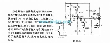
SIPMOS transistor push pull control circuit
Published:2011/4/26 2:56:00 Author:May | Keyword: SIPMOS transistor, push pull control | From:SeekIC

Input end of this circuit is connected integrated circuit TDA4700. When its output transistor turns on, base of T1 has voltage which is determined by R1, R2. Diode D1 and D2 is used to prevent the over saturation of T1. If output transistor of TDA4700 is cut off, T1 is cut off, T2 is controlled by R4, at this time, SIPMOS transistor input capacitor (crossover in the justified of R5 and T2) is as limiting resistor. The current consume of this circuit is very small because it adopts push pull control mode.
Reprinted Url Of This Article:
http://www.seekic.com/circuit_diagram/Control_Circuit/SIPMOS_transistor_push_pull_control_circuit.html
Print this Page | Comments | Reading(3)

Article Categories
power supply circuit
Amplifier Circuit
Basic Circuit
LED and Light Circuit
Sensor Circuit
Signal Processing
Electrical Equipment Circuit
Control Circuit
Remote Control Circuit
A/D-D/A Converter Circuit
Audio Circuit
Measuring and Test Circuit
Communication Circuit
Computer-Related Circuit
555 Circuit
Automotive Circuit
Repairing Circuit
Code: