Control Circuit
Relay driver circuit with the power voltage lower than the relay closing voltage
Published:2011/6/21 7:02:00 Author:TaoXi | Keyword: Relay, driver circuit, power voltage, relay closing voltage | From:SeekIC
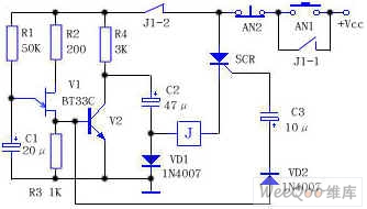
As the figure shows, the V1 is the single junction transistor BT33C, the relaxation type oscillator is composed of the R1, R2, R3 and C1, the SCR is the single-way SCR, after you press the button AN1, the circuit has the power, because the SCR has no trigger voltage, so it will not conduct, also the relay J will not work, the power supply charges the capacitance C2 to the power voltage through R4 and VD1 (Vcc-VD1 pressure drop). At the same time, the power supply charges the capacitance C1 through R1. After a few seconds, the voltage of C1 is charged to the trigger voltage of V1, so C1 discharges immediately through V1, a positive pulse is formed on R3 and this pulse adds to the base electrode of V2, so V2 conducts, the collector electrode of V2 (positive electrode of capacitance C2) is connected with the ground.
Reprinted Url Of This Article:
http://www.seekic.com/circuit_diagram/Control_Circuit/Relay_driver_circuit_with_the_power_voltage_lower_than_the_relay_closing_voltage.html
Print this Page | Comments | Reading(3)

Article Categories
power supply circuit
Amplifier Circuit
Basic Circuit
LED and Light Circuit
Sensor Circuit
Signal Processing
Electrical Equipment Circuit
Control Circuit
Remote Control Circuit
A/D-D/A Converter Circuit
Audio Circuit
Measuring and Test Circuit
Communication Circuit
Computer-Related Circuit
555 Circuit
Automotive Circuit
Repairing Circuit
Code: