Control Circuit
Relay Economy Circuit
Published:2013/10/10 20:12:00 Author:lynne | Keyword: Relay Economy Circuit | From:SeekIC


Relays continue to be useful and popular, but in low-power, battery operated applications they tend to be power wasters. The following relay economy circuits reduce coil power significantly by simply adding a series resistor. As soon as the relay picks up, the coil voltage is reduced either by the normally closed contact opening or the charging of a capacitor that is connected in parallel with the economy resistor. Included is the standard relay economy circuit as well as two additional circuits that may be new to the world.
Note that these relay economy circuits may be used in conjunction with the relay driver circuits previously posted: www.electroschematics.com/7123/relay-driver-2/
Figures 1 & 2 show how high and low side drivers can be connected to provide relay economy. The unused normally open relay contact provides the output. If an isolated contact is required, a two pole relay must be used as in figure 3.
Figures 4 & 5 solve the problem by simply adding a capacitor in parallel with the resistor. This allows the use of a single pole relay. The required capacitance is high, but voltage is low so that the size is physically manageable.
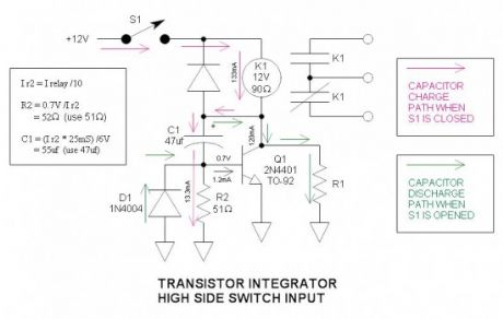
Figure 6 shows how to reduce the capacitor size by a factor of 20 by use of a simple transistor integrator. The collector voltage of Q1 integrates to the maximum voltage allowed by R1 in about 25mS.
Red arrows indicate capacitor charge pathGreen arrows indicate capacitor discharge pathC1 integrates slowly due to the limited current flowing through R2. The voltage across R2 is limited by the Vbe of Q1 (0.7V) while integrating.
Reprinted Url Of This Article:
http://www.seekic.com/circuit_diagram/Control_Circuit/Relay_Economy_Circuit.html
Print this Page | Comments | Reading(3)

Article Categories
power supply circuit
Amplifier Circuit
Basic Circuit
LED and Light Circuit
Sensor Circuit
Signal Processing
Electrical Equipment Circuit
Control Circuit
Remote Control Circuit
A/D-D/A Converter Circuit
Audio Circuit
Measuring and Test Circuit
Communication Circuit
Computer-Related Circuit
555 Circuit
Automotive Circuit
Repairing Circuit
Code: