Control Circuit
Relay Driver Circuit 2
Published:2013/10/16 20:20:00 Author:lynne | Keyword: Relay Driver Circuit 2 | From:SeekIC

Relays have been around for a long time and though often now replaced with solid state switches, they have unique properties that make them more robust than solid-state devices and are not going away. The unique properties are high current capacity, ability to withstand ESD and drive circuit isolation.
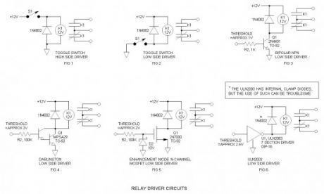
There are numerous ways to drive relays. In preparation for some of the more advanced relay drivers I will be posting in the future, I have listed a few basic relay drivers for your reference. Included are the following: High side toggle switch driver, low side toggle switch driver, bipolar NPN transistor driver, Darlington transistor driver, N-Channel MOSFET driver, and ULN2003 driver.
Relay Driver Schematic
Advantages of the low side driver
Easy to interface to low voltage logic circuitry
Far more interface options including the popular ULN2003 driver
Fewer components
Uses more commonly available and less expensive NPN drive transistors
Relay power may be sourced by a higher, unregulated voltage—reduces load on voltage regulator
Easier to interface relay economy feature—will be discussing this in the future
Industry standard technique
Relay driver, how it works?
Generally, we think on the high side because we usually place the power switch in the power lead as in Fig 1. The same may be accomplished by locating the switch in the low side or return lead as in Fig 2. When controlling relays via logic etc. it is far easier to interface to the low-side driver. For low power relays, a 2N4401 is a good choice (Fig 3). If you desire to drive a larger relay or want less base current, a Darlington driver (Fig 4) is recommended. If driving via CMOS logic, an enhancement mode MOSFET is a good choice (Fig 5). If you nave a number of relays or other loads to drive (like a 7 segment LED display), the ULN2003 is a great choice. (Fig 6).
Clamp diode
The clamp, free-wheeling or commutation diode provides a path for the inductive discharge current to flow when the driver switch is opened. If not provided, it will generate an arc in the switch—while the arc will not generally damage a switch contact, it will cause contact degradation over time—and yes, it will destroy transistors—been there, done that. The diode requirements are non-critical and a 1N4148 signal diode will generally work OK in low power applications.
The ULN2003 has internal clamp diodes. While these work OK in non-critical applications, I have had problems with them generating “glitches” in supposedly unrelated sections.
Avoid emitter follower drivers
I have not included an example of this because I do not wish to promote this technique. This is a high-side driver accomplished by an emitter follower transistor. They are frequently found on electroschematics.com, but they are not the driver of choice for three reasons as follows:
It turns the relay itself into a voltage threshold detection device—while it may work, it was not designed for this function and the threshold may vary greatly from device to device.
The emitter follower transistor requires a base drive voltage that should go essentially to the positive rail or the relay may not pick up. Only relays that have a low pick-up voltage work OK.
The voltage hysteresis is extreme—once turned on, it is often difficult to turn off again.
For the future
Relay economy driver circuits
Voltage doubler relay driver
Glossary of undocumented words and idioms (for our ESL friends)
glitch –undesirable noise transient or spike (in electronics)
Reprinted Url Of This Article:
http://www.seekic.com/circuit_diagram/Control_Circuit/Relay_Driver_Circuit_2.html
Print this Page | Comments | Reading(3)

Article Categories
power supply circuit
Amplifier Circuit
Basic Circuit
LED and Light Circuit
Sensor Circuit
Signal Processing
Electrical Equipment Circuit
Control Circuit
Remote Control Circuit
A/D-D/A Converter Circuit
Audio Circuit
Measuring and Test Circuit
Communication Circuit
Computer-Related Circuit
555 Circuit
Automotive Circuit
Repairing Circuit
Code: