Relay Control
Ordinary fan circuit
Published:2011/7/5 10:36:00 Author:John | Keyword: Ordinary fan | From:SeekIC

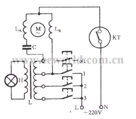
The figure shows the 400mm ordinary fan circuit. In the figure, M and LA, LR are respectively the single-phase motor rotor, the auxiliary winding and main winding. C is the starting capacitor and L is the governor. H is the indicator. The 1,2,3 all indicate the wind speed gear switch, which is respectively marked as high, medium and low speed gear.
Reprinted Url Of This Article:
http://www.seekic.com/circuit_diagram/Control_Circuit/Relay_Control/Ordinary_fan_circuit.html
Print this Page | Comments | Reading(3)

Article Categories
power supply circuit
Amplifier Circuit
Basic Circuit
LED and Light Circuit
Sensor Circuit
Signal Processing
Electrical Equipment Circuit
Control Circuit
Remote Control Circuit
A/D-D/A Converter Circuit
Audio Circuit
Measuring and Test Circuit
Communication Circuit
Computer-Related Circuit
555 Circuit
Automotive Circuit
Repairing Circuit
Code: