Control Circuit
ROOM_HEATER_CONTROL
Published:2009/7/8 1:57:00 Author:May | From:SeekIC

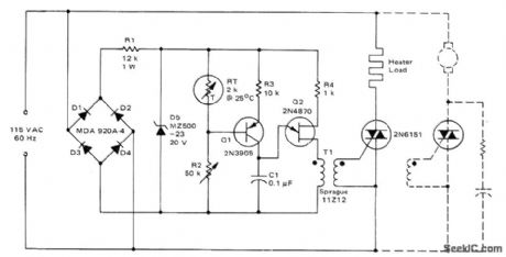
Use of phase control for triac provides gradual reduction in heater load current as desired temperature is approached, eliminating large overshoots. R2 is adjusted so al is of at desired temperature, turning Q2 off and preventing firing of triac. If temperature decreases, resistance of sensor RT increases and transistors initiate firing of triac.If RT continues to increase, C1 charges faster and triac is triggered earlier in each half-cycle, delivering more power to load. Dashed Iines indicate alternate connections for controlling motor with constant load such as blower motor. For cooling applications, interchange FIT and R2.- Circuit Applications for the Triac, Motorola, Phoenix, AZ, 1971, AN-466, p 9.
Reprinted Url Of This Article:
http://www.seekic.com/circuit_diagram/Control_Circuit/ROOM_HEATER_CONTROL.html
Print this Page | Comments | Reading(3)

Article Categories
power supply circuit
Amplifier Circuit
Basic Circuit
LED and Light Circuit
Sensor Circuit
Signal Processing
Electrical Equipment Circuit
Control Circuit
Remote Control Circuit
A/D-D/A Converter Circuit
Audio Circuit
Measuring and Test Circuit
Communication Circuit
Computer-Related Circuit
555 Circuit
Automotive Circuit
Repairing Circuit
Code: