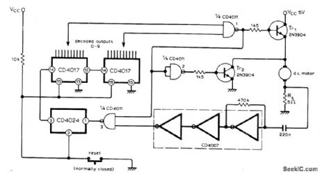
Control Circuit
REVOLUTION_COUNTING_CONTROL
Published:2009/7/7 2:59:00 Author:May | From:SeekIC

When desired number of revolutions is reached by DC motor, as determined by preset counter, Tr1, is turned off to interrupt path to 5-V motor supply, while TR2 is turned on to brake motor rapidly. Voltage developed across 5-ohm resistor Rs, in series with motor contains frequency component related to speed of rotation and number of armature coils. This signal is amplified by CD4007 CMOS inverter for feeding to counters through signal-squaring inverters. Counter out-puts are decoded by gate 1. Motor slowdown by heavy loads does not affect accuracy of revolution-counting.-R. McGillivray, Motor Revolutions Control, Wireless World, Jan. 1977, p 76.
Reprinted Url Of This Article:
http://www.seekic.com/circuit_diagram/Control_Circuit/REVOLUTION_COUNTING_CONTROL.html
Print this Page | Comments | Reading(3)

Article Categories
power supply circuit
Amplifier Circuit
Basic Circuit
LED and Light Circuit
Sensor Circuit
Signal Processing
Electrical Equipment Circuit
Control Circuit
Remote Control Circuit
A/D-D/A Converter Circuit
Audio Circuit
Measuring and Test Circuit
Communication Circuit
Computer-Related Circuit
555 Circuit
Automotive Circuit
Repairing Circuit
Code: