Protection Circuit
NE555 Overvoltage and Overcurrent Protection Circuit
Published:2011/6/23 10:10:00 Author:Michel | Keyword: Overvoltage, Overcurrent, Protection Circuit | From:SeekIC
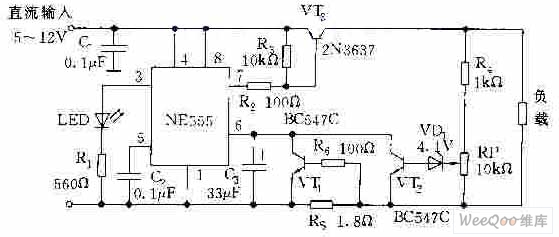
The picture is the overvoltage and overcurrent protection circuit composed of NE555. VT1 and VT ends, NE555 resets, and all of the transistor is in conduction mode.It absorbs current from VT3 which makes VT stay in saturation condition and 5~12V DC power supply provides load via VT3.When load current exceeds rating value and voltage on RS increases which makes VT1 conduct and NE555 be triggered and then VT3 stops,load power supply cuts off.At the time,NE555 is in monostable condition and NE555 is triggered again VT3 continuely isolates load from power supply as long as the load flow does not rule out.
Reprinted Url Of This Article:
http://www.seekic.com/circuit_diagram/Control_Circuit/Protection_Circuit/NE555_Overvoltage_and_Overcurrent_Protection_Circuit.html
Print this Page | Comments | Reading(3)

Article Categories
power supply circuit
Amplifier Circuit
Basic Circuit
LED and Light Circuit
Sensor Circuit
Signal Processing
Electrical Equipment Circuit
Control Circuit
Remote Control Circuit
A/D-D/A Converter Circuit
Audio Circuit
Measuring and Test Circuit
Communication Circuit
Computer-Related Circuit
555 Circuit
Automotive Circuit
Repairing Circuit
Code: