Protection Circuit
Motor protector circuit diagram 9
Published:2011/6/13 23:38:00 Author:Lucas | Keyword: Motor protector | From:SeekIC

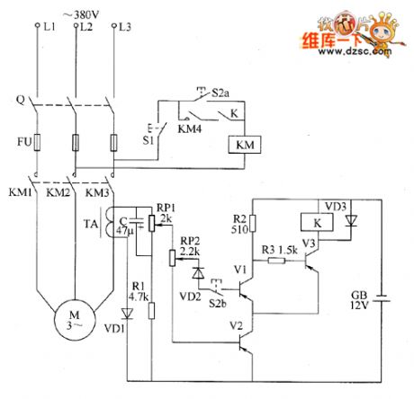
The motor protection circuit is composed of the start control circuit, phase detection circuit and protection implementation circuit, the circuit is shown as the chart. Control circuit is composed of starter button S2 and stop button S1 and so on. Phase failure detection circuit consists of the current transformer coil TA, rectifier diode VD1, resistor R1, capacitor C and potentiometers RP1 and RP2 and so on. Protection implementation circuit is composed of the transistors V1 ~ V3, relay K, AC contactor KM and other components. Pressing the start button S2 (S2a and linkage 52b) will make the AC contactor KM and its normally open contacts (moving together contact) KM1 ~ KM4 pull in, the motor M operates to generate 1.2V induced voltage in ⒕, the voltage is rectified by VD1 to make V2 be saturated conduction. At this point, the 52b is off, V1 stops, V3 turns on, relay K pulls in and works, its normally open contact Κ is connected, hands being away the start button S2 will maintain the normal operation of motor M.
Reprinted Url Of This Article:
http://www.seekic.com/circuit_diagram/Control_Circuit/Protection_Circuit/Motor_protector_circuit_diagram_9.html
Print this Page | Comments | Reading(3)

Article Categories
power supply circuit
Amplifier Circuit
Basic Circuit
LED and Light Circuit
Sensor Circuit
Signal Processing
Electrical Equipment Circuit
Control Circuit
Remote Control Circuit
A/D-D/A Converter Circuit
Audio Circuit
Measuring and Test Circuit
Communication Circuit
Computer-Related Circuit
555 Circuit
Automotive Circuit
Repairing Circuit
Code: