Protection Circuit
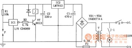
Home booster pump protection circuit diagram
Published:2011/8/2 2:37:00 Author:Rebekka | Keyword: Home booster pump protection | From:SeekIC

The power supply switch S will be closed if the water pipe has not water, P and the ground is similar to insulation condition, the inverter ICl inputs high, outputs low, VT cuts off, J is released. Its tragger J-1 cuts off, M booster pump is not running avoiding pump idling. If the pipe has water, P and steel shell pass the water and resistance will be conducted, then ICl input is low level and output is high level, VT will be conducted, J pulls in, M operates normally. IC1 uses CD4069 six-inverter, the one shown in the figure only uses one group of inverters, and the rest 5 groups of inverters is vacant(Connect all the input ends to the ground to prevent interference.) P is the detection sensor when there is not water, you need to make it by yourself. Methods: Drill a hole in the pipe, spark plugs into the car, pay attention to the pad to prevent leakage, eads to P pole at the spark needle, water pipe(steel) chassis can connect to the ground.
Reprinted Url Of This Article:
http://www.seekic.com/circuit_diagram/Control_Circuit/Protection_Circuit/Home_booster_pump_protection_circuit_diagram.html
Print this Page | Comments | Reading(3)

Article Categories
power supply circuit
Amplifier Circuit
Basic Circuit
LED and Light Circuit
Sensor Circuit
Signal Processing
Electrical Equipment Circuit
Control Circuit
Remote Control Circuit
A/D-D/A Converter Circuit
Audio Circuit
Measuring and Test Circuit
Communication Circuit
Computer-Related Circuit
555 Circuit
Automotive Circuit
Repairing Circuit
Code: