Control Circuit
Photosensitive alarm circuit
Published:2011/7/4 4:01:00 Author:Christina | Keyword: Photosensitive alarm | From:SeekIC

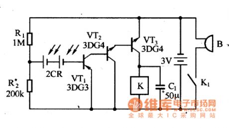
The photosensitive alarm circuit is as shown in the figure. The R1 and R2 are the partial voltage bias circuits. When there is no illumination, the silicon photocell will not produce the voltage, it only the resistance which is connected in the base circuit of the amplifier. When there is the illumination, the silicon photocell will produce the voltage, this voltage and the ground voltage add to the base electrode of VT1 together, so the VT1, VT2 and VT3 conduct, the relay K starts working, the contact point closes, the buzzer sends out the alarm.
This alarm circuit can be used in the anti-theft alarm of the drawer cabinet.
Figure:Photosensitive alarm circuit
Reprinted Url Of This Article:
http://www.seekic.com/circuit_diagram/Control_Circuit/Photosensitive_alarm_circuit.html
Print this Page | Comments | Reading(3)

Article Categories
power supply circuit
Amplifier Circuit
Basic Circuit
LED and Light Circuit
Sensor Circuit
Signal Processing
Electrical Equipment Circuit
Control Circuit
Remote Control Circuit
A/D-D/A Converter Circuit
Audio Circuit
Measuring and Test Circuit
Communication Circuit
Computer-Related Circuit
555 Circuit
Automotive Circuit
Repairing Circuit
Code: