Control Circuit
PIN diode switch circuit
Published:2011/6/19 10:48:00 Author:John | Keyword: diode, switch | From:SeekIC

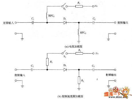
In the circuit shown in Figure (a), the diode Dy and the signal line are used in series. When the diode conducts, the signal path is with low resistance. When the diode closes, it presents a high resistance (so as to achieve the switching function). When the switch S opens, the diode is not biased. The circuit has been disconnected because of the diode’s impedance. When S closes, the diode is forward biased and the resistance of signal channel is very low. The impedance ratio by the state of opening and closing is a measure of isolation for the circuit.
Reprinted Url Of This Article:
http://www.seekic.com/circuit_diagram/Control_Circuit/PIN_diode_switch_circuit.html
Print this Page | Comments | Reading(3)

Article Categories
power supply circuit
Amplifier Circuit
Basic Circuit
LED and Light Circuit
Sensor Circuit
Signal Processing
Electrical Equipment Circuit
Control Circuit
Remote Control Circuit
A/D-D/A Converter Circuit
Audio Circuit
Measuring and Test Circuit
Communication Circuit
Computer-Related Circuit
555 Circuit
Automotive Circuit
Repairing Circuit
Code: