Control Circuit
PIEZOELECTRIC_FAN_BASED_TEMPERATURE_CONTROLLER
Published:2009/7/7 23:18:00 Author:May | From:SeekIC

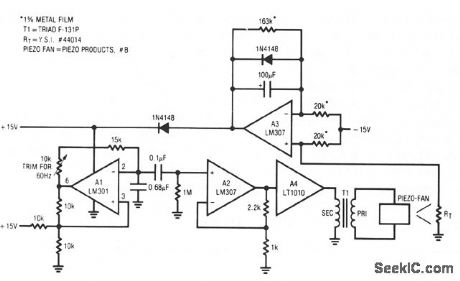
The fan employed is one of the new electrostatic type which is very retable, because it contains no wearing parts. These devices require high-voltage drive. When power is applied, the thermistor, located in the fan's exhaust stream, is at a high value. This value unbalances the A3 amplifier driven bridge. A1 receives no power and the fan does not run. As the instrument enclosure warms, the thermistor value decreases until A3 begins to oscillate. A2 provides isolation and gain, and A4 drives the transformer to generate high voltage for the fan. In this fashion, the loop acts to maintain a stable instrument temperature by controlling the fm's exhaust rate. The 100-μF time constant across the error amplifier pins is typical of such configurations. Fast time constants will produce audibly annoying hunting in the servo. Optimal values for this time constant and gain depend upon the thermal and airflow characteristics of the enclosure being controlled.
Reprinted Url Of This Article:
http://www.seekic.com/circuit_diagram/Control_Circuit/PIEZOELECTRIC_FAN_BASED_TEMPERATURE_CONTROLLER.html
Print this Page | Comments | Reading(3)

Article Categories
power supply circuit
Amplifier Circuit
Basic Circuit
LED and Light Circuit
Sensor Circuit
Signal Processing
Electrical Equipment Circuit
Control Circuit
Remote Control Circuit
A/D-D/A Converter Circuit
Audio Circuit
Measuring and Test Circuit
Communication Circuit
Computer-Related Circuit
555 Circuit
Automotive Circuit
Repairing Circuit
Code: