Control Circuit
Motorcycle Speed Indicator (2)
Published:2011/7/9 6:10:00 Author:Sue | Keyword: Motorcycle, Speed Indicator | From:SeekIC

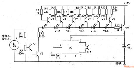
The motorcycle alternator(speed detection alternator)'s output voltage will serve as V1's and V2's bias voltage after it is voltage divided by R1,RP. The voltage will control the working states of V1,V2. The faster the motorcycle is running, the higher the alternator's output voltage will be, the higher the bias voltage will be, the stronger V1's and V2's conducting ability will be, the more illuminated lights of VL1-VL6 will be.
When the motorcycle begins to run, VL1-VL6 are all illuminated and V3-V9 are all connected. IC obtains working voltage which can drive HA to make an alarm sound to warn the driver that The motorcycle has exceeds the speed limit. Please slow down .
By adjusting RP's resistance value, VL1 will be illuminated when the speed is 10km/h. When the speed is 60km/h, the illuminations are all illuminated. When the speed exceeds 70km/h, there will be an alarm.
Reprinted Url Of This Article:
http://www.seekic.com/circuit_diagram/Control_Circuit/Motorcycle_Speed_Indicator_2.html
Print this Page | Comments | Reading(3)

Article Categories
power supply circuit
Amplifier Circuit
Basic Circuit
LED and Light Circuit
Sensor Circuit
Signal Processing
Electrical Equipment Circuit
Control Circuit
Remote Control Circuit
A/D-D/A Converter Circuit
Audio Circuit
Measuring and Test Circuit
Communication Circuit
Computer-Related Circuit
555 Circuit
Automotive Circuit
Repairing Circuit
Code: