Control Circuit
Motorcycle Speed Indicator (1)
Published:2011/7/9 5:41:00 Author:Sue | Keyword: Motorcycle, Speed Indicator | From:SeekIC

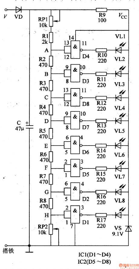
The alternator's output voltage V(It is achieved from ac voltage output from the alternator's head lamp's supply winding) will be divided into two circuits after it is rectificated by VD, filtrated by C. One circuit will provide IC2,IC1 and VL1-VL8 with 9v voltage after it is limited by R9, stablized by VS. The other circuit will generate 8 different detect voltage on A-H terminals after it is voltage divided by the voltage division circuit. When one terminal's detect voltage reaches NOT GATE circuit's threshold level, the NOT GATE circuit will output low level, which will make its output terminals outside circuit's diodes illuminated. The motorcycle rider can get to know the current motorcycle speed by the number and standard of illuminated diodes.
Reprinted Url Of This Article:
http://www.seekic.com/circuit_diagram/Control_Circuit/Motorcycle_Speed_Indicator_1.html
Print this Page | Comments | Reading(3)

Article Categories
power supply circuit
Amplifier Circuit
Basic Circuit
LED and Light Circuit
Sensor Circuit
Signal Processing
Electrical Equipment Circuit
Control Circuit
Remote Control Circuit
A/D-D/A Converter Circuit
Audio Circuit
Measuring and Test Circuit
Communication Circuit
Computer-Related Circuit
555 Circuit
Automotive Circuit
Repairing Circuit
Code: