Control Circuit
Motor protector 7
Published:2011/6/27 20:52:00 Author:Nicole | Keyword: Motor, protector | From:SeekIC

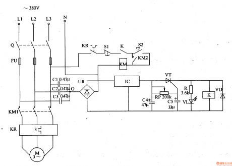
When the three-phase power supply is normal, the common contact 0 of detection capacitors C1-C3 has no current, the both sides of C4 has no voltage, thyristor VT is in off state, relay K does not pull in, the normally closed contact K is turned on, LED VL does not light, motor M works normally.
KP is heat relay, S1 is stop button, S2 is starter button, R is current limiting resistor.
The delay circuit is composed of potentiometer RP, capacitor C5 or thyristor VT, it can prevent protector from wrong actions due to serious harmonic interference or instantaneous voltage fluctuation.
Reprinted Url Of This Article:
http://www.seekic.com/circuit_diagram/Control_Circuit/Motor_protector_7.html
Print this Page | Comments | Reading(3)

Article Categories
power supply circuit
Amplifier Circuit
Basic Circuit
LED and Light Circuit
Sensor Circuit
Signal Processing
Electrical Equipment Circuit
Control Circuit
Remote Control Circuit
A/D-D/A Converter Circuit
Audio Circuit
Measuring and Test Circuit
Communication Circuit
Computer-Related Circuit
555 Circuit
Automotive Circuit
Repairing Circuit
Code: