Control Circuit
Motor protector 4
Published:2011/6/27 5:07:00 Author:Nicole | Keyword: Motor, protector | From:SeekIC

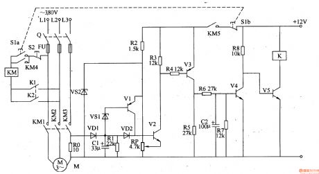
This motor protector circuit is composed of current detection control circuit and delay control circuit, it is shown in the figure 8-40.
The current detection control circuit is made of resistors R0-R5, transistors V1-V3, capacitor C1, diodes VD1, VD2 and Zener diode VS1, VS2.
The delay control circuit consists of resistors R6-R8, capacitor C2, transistors V4, V5 and relay K.
S1 is starter button, S2 is stop button, KM is AC contactor.
After S1 is pressed, V5 is saturation conduction, K pulls in, its normally open contacts K1, K2 are turned on, KM action makes motor M operated, at the same time, the current detection control circuit starts to work.
Reprinted Url Of This Article:
http://www.seekic.com/circuit_diagram/Control_Circuit/Motor_protector_4.html
Print this Page | Comments | Reading(3)

Article Categories
power supply circuit
Amplifier Circuit
Basic Circuit
LED and Light Circuit
Sensor Circuit
Signal Processing
Electrical Equipment Circuit
Control Circuit
Remote Control Circuit
A/D-D/A Converter Circuit
Audio Circuit
Measuring and Test Circuit
Communication Circuit
Computer-Related Circuit
555 Circuit
Automotive Circuit
Repairing Circuit
Code: