Control Circuit
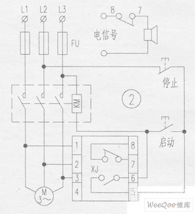
Motor phase broken phase protector circuit
Published:2011/6/24 1:28:00 Author:TaoXi | Keyword: Motor phase, broken phase, protector circuit | From:SeekIC


Working principle:
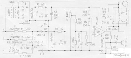
The A, B, C are connected with the A, B, C phases of the AC380V power line network, the phase-shift circuit is composed of the R1, R4, R2, R5, C1, R3, R6, R16, R17, C6. When the voltage is normal (the phase sequence is correct and no phase-lack), the vector voltage of the rectifier input port which is composed of the diodes D5, D7, D8, D13 is small, the rectified voltage is small too. When the phase sequence is wrong or the phase is incomplete, the output voltage instantaneous up to 13V. The voltage is filted by V4, limited by R8 and then is stabilized by D9, at last it is send to the pin-2 of the comparator LM358 through the current limiting resistor R12, it is used as the detected signal voltage.
Reprinted Url Of This Article:
http://www.seekic.com/circuit_diagram/Control_Circuit/Motor_phase_broken_phase_protector_circuit.html
Print this Page | Comments | Reading(3)

Article Categories
power supply circuit
Amplifier Circuit
Basic Circuit
LED and Light Circuit
Sensor Circuit
Signal Processing
Electrical Equipment Circuit
Control Circuit
Remote Control Circuit
A/D-D/A Converter Circuit
Audio Circuit
Measuring and Test Circuit
Communication Circuit
Computer-Related Circuit
555 Circuit
Automotive Circuit
Repairing Circuit
Code: