Control Circuit
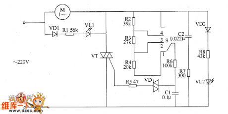
Motor electronic speed controller circuit diagram 5
Published:2011/5/18 6:43:00 Author:Lucas | Keyword: Motor , electronic speed controller | From:SeekIC

The motor electronic speed controller circuit consists of intergranular tube VT, diode VD1, VD2, bidirectional trigger diode VD, LEDs VL1, VL2, capacitors GI, C2, resistors R1 ~ R8, speed control switch S, motor M and so on, the circuit is shown as the chart. Changing the gear of S speed switch can change the charging and discharging rate of capacitor C1, thereby the thyristor conduction angle of thyristor VT is changed. The voltage on the two ends of C1 can trigger VT and make it turn on by VD, the AC voltage across the motor M is controlled by changing the conduction angle, thus the M's running speed is changed. VL1 and VL2 are the working status indicator LEDs. When S is placed on the 1 block, VL2 is lit; when the S is placed on the 4 block, VL1 is lit.
Reprinted Url Of This Article:
http://www.seekic.com/circuit_diagram/Control_Circuit/Motor_electronic_speed_controller_circuit_diagram_5.html
Print this Page | Comments | Reading(3)

Article Categories
power supply circuit
Amplifier Circuit
Basic Circuit
LED and Light Circuit
Sensor Circuit
Signal Processing
Electrical Equipment Circuit
Control Circuit
Remote Control Circuit
A/D-D/A Converter Circuit
Audio Circuit
Measuring and Test Circuit
Communication Circuit
Computer-Related Circuit
555 Circuit
Automotive Circuit
Repairing Circuit
Code: