© 2008-2012 SeekIC.com Corp.All Rights Reserved.
Control Circuit
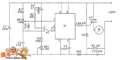
Motor electronic speed controller circuit diagram 4
Published:2011/5/18 6:51:00 Author:Lucas | Keyword: Motor , electronic speed controller | From:SeekIC

The motor speed controller circuit consists of power circuit, timing control / trigger pulse generator circuit and control implementation circuit, the circuit is shown as the chart. Power supply circuit consists of step-down capacitor C5, voltage regulator diode VS, rectifier diode VD2, filter capacitor C1. Timer control / trigger pulse generator circuit is composed of the time-base integrated circuit IC, the control switch S1, timer / voltage selecting switch S2, resistors R1 ~ R3, potentiometers RP1, RP2, capacitors C2 ~ C4. Control implementation circuit is composed of the resistor M and thyristor VT. AC 220V voltage is bucked by C5, stabilized by resistor R5, VS, rectified by VD2 and filtered by C1 to provide 121V (Vcc) DC working voltage for IC. R1 ~ R5 use 1/4W carbon film resistors or metal film resistors.
Reprinted Url Of This Article:
http://www.seekic.com/circuit_diagram/Control_Circuit/Motor_electronic_speed_controller_circuit_diagram_4.html
Print this Page | Comments | Reading(3)

Article Categories
power supply circuit
Amplifier Circuit
Basic Circuit
LED and Light Circuit
Sensor Circuit
Signal Processing
Electrical Equipment Circuit
Control Circuit
Remote Control Circuit
A/D-D/A Converter Circuit
Audio Circuit
Measuring and Test Circuit
Communication Circuit
Computer-Related Circuit
555 Circuit
Automotive Circuit
Repairing Circuit
New published articles
Response in 12 hours

Code: