Control Circuit
Low Drift Differentiator Circuit
Published:2011/7/22 7:29:00 Author:Sue | Keyword: Low Drift, Differentiator | From:SeekIC


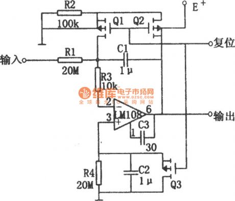
The differentiator shown in the circuit has small drift which will not exceed 500μV/s within the temperature rangefrom -55C to +125C. In the picture, the basic differentiator consists of operational amplifier, resistor R1 and capacitor C1. In order to improve the stability of the differentiator, the circuit adds resistor R4 and capacitor C2(R4=R1,C2=C1) to the operational amplifier's non inverting input terminal which will differentiate the input bias current. When the circuit is reset, field effec tube Q1 and Q2 will make the capacitor C1 short, which will prevent the input bias current from causing offset voltage. When Q1 and Q2are disconnected, the circuit begins to integrate. Then the bias current which flows through R1 will generate offset voltage.
Reprinted Url Of This Article:
http://www.seekic.com/circuit_diagram/Control_Circuit/Low_Drift_Differentiator_Circuit.html
Print this Page | Comments | Reading(3)

Article Categories
power supply circuit
Amplifier Circuit
Basic Circuit
LED and Light Circuit
Sensor Circuit
Signal Processing
Electrical Equipment Circuit
Control Circuit
Remote Control Circuit
A/D-D/A Converter Circuit
Audio Circuit
Measuring and Test Circuit
Communication Circuit
Computer-Related Circuit
555 Circuit
Automotive Circuit
Repairing Circuit
Code: