Control Circuit
Intelligent alarm system audio circuit diagram
Published:2011/3/31 22:31:00 Author:Rebekka | Keyword: Intelligent alarm system, audio circuit | From:SeekIC

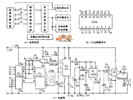
The alarm system will shows the floor and the room number of the steal and uses sound-light alarm. The block diagram of the system is shown in figure A. The sensor of the system uses Pyroelectric infrared control module. The power supply uses AC and DC automatically converted power supply. The audio alarm circuit of the system is shown in figure C. It is specially designed for the system. The Address matrix control circuit shown in figure A uses 2 manual button data transmission integrated circuits C306(shown in figure B). It has 11~19 input terminals and 4 output terminals, A, B, C, D. Usually, connecting 11~19 input terminals to ground potential through resistance. The output terminals ABCD are 0000 . When a steal happens, one input terminal will be at a high potential. If the terminal 13 is at a high potential, the output BCD code is 0011 . The decimal number is 3 . The matrix display(shown the floor and room number) panel is composed of 2 C403 and routing matrix. Figure C is an audio alarm circuit. It is composed of a C403 A, B, C output terminals. When a steal happens, one of the 11~14 output terminals will turn to a high potencial. One of the A, B, C terminals will turn to a high potencial. The gate circuit will enable VT1 saturate and turn on. The negative pulse transition of integrated electrodes will make monostable trigger circuit IC3 turn to a high potencial output. It will offer a working circuit for IC4.
Reprinted Url Of This Article:
http://www.seekic.com/circuit_diagram/Control_Circuit/Intelligent_alarm_system_audio_circuit_diagram.html
Print this Page | Comments | Reading(3)

Article Categories
power supply circuit
Amplifier Circuit
Basic Circuit
LED and Light Circuit
Sensor Circuit
Signal Processing
Electrical Equipment Circuit
Control Circuit
Remote Control Circuit
A/D-D/A Converter Circuit
Audio Circuit
Measuring and Test Circuit
Communication Circuit
Computer-Related Circuit
555 Circuit
Automotive Circuit
Repairing Circuit
Code: