Control Circuit
Illumination Controller (36)
Published:2011/7/7 7:24:00 Author:Sue | Keyword: Illumination, Controller | From:SeekIC

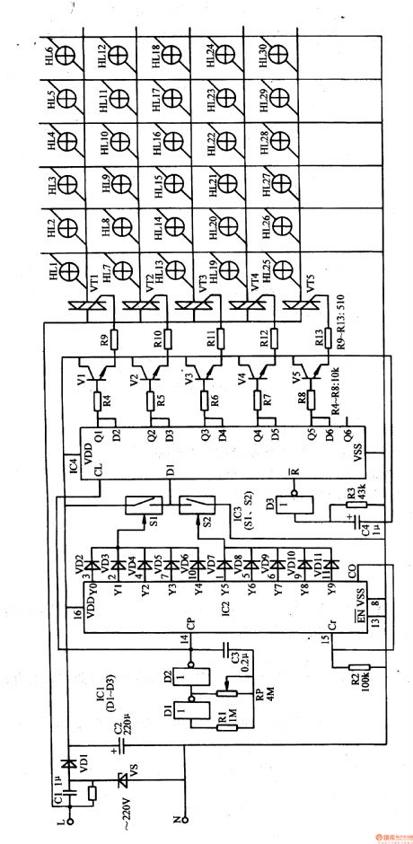
The 220v ac voltage will provide IC1-IC4 and V1-V5 with nearly 12v direct current working voltage after it is reduced by C1, stablized by VS, rectificated by VD1, filtrated by C2.
After the multivibrator begins to work, it will output oscillate pulse signals with a frequency of 2Hz which will provide IC2 with count pulse. Under the control of IC2's count pulse, Y0-Yg terminals will output high level in turn.
C4,R3,D3 will constitute IC4's reset circuit which will provide IC4 with reset pulse after it is connected. Then IC4 is reset, Q1-Q5 terminals will output low level. V1-V5 and VT1-VT5 will be disconnected. HL1-HL30 are all not illuminated.
Reprinted Url Of This Article:
http://www.seekic.com/circuit_diagram/Control_Circuit/Illumination_Controller_36.html
Print this Page | Comments | Reading(3)

Article Categories
power supply circuit
Amplifier Circuit
Basic Circuit
LED and Light Circuit
Sensor Circuit
Signal Processing
Electrical Equipment Circuit
Control Circuit
Remote Control Circuit
A/D-D/A Converter Circuit
Audio Circuit
Measuring and Test Circuit
Communication Circuit
Computer-Related Circuit
555 Circuit
Automotive Circuit
Repairing Circuit
Code: