Control Circuit
Illumination Controller (30)
Published:2011/7/7 6:07:00 Author:Sue | Keyword: Illumination, Controller | From:SeekIC

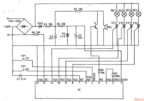
The 220v ac voltage will be put on HL1-H after it is rectificated by VD1-VD4. The other circuit will provide IC with 5v direct current working voltage after it is isolated by VD5, limited by R1,R2, filtrated by C1,C2, stablized by VS. The ac voltage is also put on IC's pin 12 after it is limited and reduced by R4. It can serve as ac synchronizing signals.
IC's pin 8-11(TG1-TG4 terminals) will serve as trigger control signals output terminals. The trigger signals output by these terminals will control the working states of VT1-VW to control the illumination modes of illumination HL1-HL4.
IC's pin 4 (BZ terminals) serve as musical signals output terminal. The musical signals can promote HA to make sound after it is amplified by V.
S1 is illumination modes control button. When S1 is pushed, illumination modes can be changed.
Reprinted Url Of This Article:
http://www.seekic.com/circuit_diagram/Control_Circuit/Illumination_Controller_30.html
Print this Page | Comments | Reading(3)

Article Categories
power supply circuit
Amplifier Circuit
Basic Circuit
LED and Light Circuit
Sensor Circuit
Signal Processing
Electrical Equipment Circuit
Control Circuit
Remote Control Circuit
A/D-D/A Converter Circuit
Audio Circuit
Measuring and Test Circuit
Communication Circuit
Computer-Related Circuit
555 Circuit
Automotive Circuit
Repairing Circuit
Code: