Control Circuit
Illumination Controller (21)
Published:2011/7/6 6:12:00 Author:Sue | Keyword: Illumination, Controller | From:SeekIC

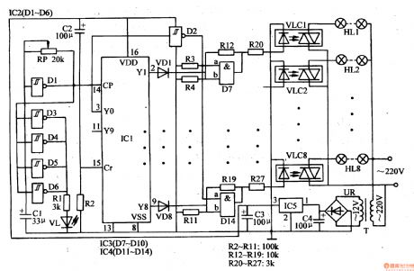
When the power is on, the 220v ac voltage will generate +9v voltage on C3 after it is reduced by T, rectificated by UR, filtrated by C4, stablized by IC5. The voltage will be provided to IC1-IC4.
The moment the power is on, +9v voltage will generate a pulse on IC1's Cr terminal(pin 15, reset terminal) through capacitor C2. Then IC1 will be reset. IC1's Y1-Y8 terminals(output terminal) will have low level. Y0 terminal has high level which will turn into low level after it is phase reversed by IC2's inside NOT gate Schmitt trigger D2. The low level will be put on IC3's inside AND GATE circuits(D1-D4) and IC4's inside AND GATE circuits'(D7-D14) a input terminal. Then AND GATE circuits D7-D14 will output low level. The optical coupler VLC1-VLC8 are all disconnected and HL1-HL8 are not illuminated.
Reprinted Url Of This Article:
http://www.seekic.com/circuit_diagram/Control_Circuit/Illumination_Controller_21.html
Print this Page | Comments | Reading(3)

Article Categories
power supply circuit
Amplifier Circuit
Basic Circuit
LED and Light Circuit
Sensor Circuit
Signal Processing
Electrical Equipment Circuit
Control Circuit
Remote Control Circuit
A/D-D/A Converter Circuit
Audio Circuit
Measuring and Test Circuit
Communication Circuit
Computer-Related Circuit
555 Circuit
Automotive Circuit
Repairing Circuit
Code: