Control Circuit
Illumination Controller (20)
Published:2011/7/6 5:54:00 Author:Sue | Keyword: Illumination, Controller | From:SeekIC

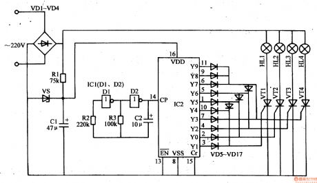
When the first count pulse is sent to IC2's pin 14, IC2's Y0-Y3 terminals output high pulse(when Y0 terminal outputs high level, Y1-Y3 terminals output low level; when Y1 terminal outputs high level, Y0,Y2,Y3 terminals output low level...and the like), VT1-VT4's inside corresponding thyristors are connected in short time. Four circuits of illuminations are illuminated in turn(when IC2's Y0 terminal outputs high level, VT1 is connected, Vm-V are disconnected. HL1 are illuminated. HL2-HLm are not illuminated. When Y2 terminal outputs high level, VT3 is connected and HL3 will be illuminated. HL2 will be off and HL1-HL4 will be off.When Y3 terminal outputs high level, VT4 are connected and HL4 will be illuminated. HL3 will be off. HL1-HL2 will be off.)
Reprinted Url Of This Article:
http://www.seekic.com/circuit_diagram/Control_Circuit/Illumination_Controller_20.html
Print this Page | Comments | Reading(3)

Article Categories
power supply circuit
Amplifier Circuit
Basic Circuit
LED and Light Circuit
Sensor Circuit
Signal Processing
Electrical Equipment Circuit
Control Circuit
Remote Control Circuit
A/D-D/A Converter Circuit
Audio Circuit
Measuring and Test Circuit
Communication Circuit
Computer-Related Circuit
555 Circuit
Automotive Circuit
Repairing Circuit
Code: