Control Circuit
Ignition Coil Driver
Published:2012/12/3 20:30:00 Author:muriel | Keyword: Ignition Coil Driver | From:SeekIC

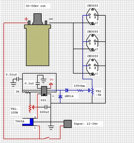
This design uses a 555 timer and three 2n3055 switching transistors to provide a variable frequency, variable voltage input to an automotive ignition coil. Normal output is 25kV when run at 12v input and at the coil's resonant frequency (8kHz). Increasing the voltage output to about 50kV is possible if the input voltage is increased to 34v, however this risks burning out the switching transistors when the system is operated for an extended time.
Electrical Diagram:
Capacitors: rated at 50v
Resistors: 1/2w, 5% tolerance
Output frequency to the coil is controlled by VR1, output voltage is controlled by VR2.
V+ is connected to pin 3 on the 5v regulator.
Reprinted Url Of This Article:
http://www.seekic.com/circuit_diagram/Control_Circuit/Ignition_Coil_Driver.html
Print this Page | Comments | Reading(3)

Article Categories
power supply circuit
Amplifier Circuit
Basic Circuit
LED and Light Circuit
Sensor Circuit
Signal Processing
Electrical Equipment Circuit
Control Circuit
Remote Control Circuit
A/D-D/A Converter Circuit
Audio Circuit
Measuring and Test Circuit
Communication Circuit
Computer-Related Circuit
555 Circuit
Automotive Circuit
Repairing Circuit
Code: