Control Circuit
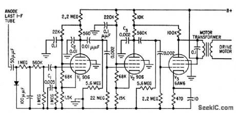
GONIOMETER_MOTOR_AMPUFIER
Published:2009/7/22 1:24:00 Author:Jessie | From:SeekIC

Portion of adf receiver output is separately rectified and applied to selective amplifier V1.V2-V3.C1, C2, and C3 develop 90° phase shift re quired between two coils of goniometer drive motor and serve also as low-pass fiber with sharp cutoff above 150 cps. Overall gain is high enough so motor will exert full torque when goniometer is only 3° off true null.-J. r. Hatch and D. W. G. Byatt, Direction Finder with Automatic Readout Electronics, 32:16, p 62-64.
Reprinted Url Of This Article:
http://www.seekic.com/circuit_diagram/Control_Circuit/GONIOMETER_MOTOR_AMPUFIER.html
Print this Page | Comments | Reading(3)

Article Categories
power supply circuit
Amplifier Circuit
Basic Circuit
LED and Light Circuit
Sensor Circuit
Signal Processing
Electrical Equipment Circuit
Control Circuit
Remote Control Circuit
A/D-D/A Converter Circuit
Audio Circuit
Measuring and Test Circuit
Communication Circuit
Computer-Related Circuit
555 Circuit
Automotive Circuit
Repairing Circuit
Code: