Control Circuit
Full Tank Alarm (2)
Published:2011/6/27 3:46:00 Author:Sue | Keyword: Full, Tank, Alarm | From:SeekIC

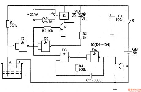
A and B are put in the tank as water level sensors. When the tank is not full, the resistance value between Aand B is large. D1's input terminal is high level while its output terminal is low level. V is disconnected. K is released. K's nornally closed interlock is connected. M begins to work. Then D2 outputs high level and VL is not illuminated. The oscillator composed of D3 D4 R4 C2 doesn't work and HA makes no sound.
When the water level reaches B, D1's input terminal is low level and its output terminal is high level. V is connected and K is connected. M stops working. Then D2 outputs low level, and VL is illuminated. The oscillator begins to work and HA makes an alarm sound.
Reprinted Url Of This Article:
http://www.seekic.com/circuit_diagram/Control_Circuit/Full_Tank_Alarm_2.html
Print this Page | Comments | Reading(3)

Article Categories
power supply circuit
Amplifier Circuit
Basic Circuit
LED and Light Circuit
Sensor Circuit
Signal Processing
Electrical Equipment Circuit
Control Circuit
Remote Control Circuit
A/D-D/A Converter Circuit
Audio Circuit
Measuring and Test Circuit
Communication Circuit
Computer-Related Circuit
555 Circuit
Automotive Circuit
Repairing Circuit
Code: