Control Circuit
Fast_charge_controllers_for_NiCcld_NiMH
Published:2009/7/27 0:25:00 Author:Jessie | From:SeekIC


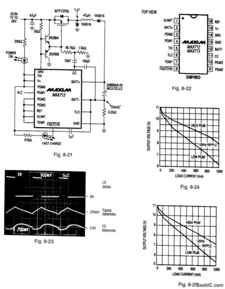
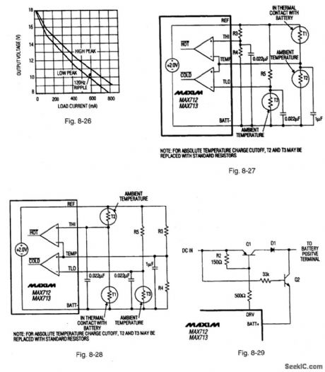
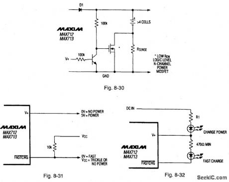
Figure 8-21 shows a MAX713 connected to provide a fast charge for two cells at 1 A. Higher charge currented and greater number of cells can be accommodated by changing RSENSE and the PGMO-PCM3 connections (as described in the date sheet).Figure 8-22 shows the pin connections and Fig. 8-23 shows the circuit waveforms. Notice that the circuit of Fig. 8-21 cannot service a loud while charging. The Fig. 8-21 circuit is usually used with an ac-to-dc wall cube (transformer,bridge rectifier, and capactior in a plug-in package).Figures 8-24.8-25,and 8-26 show the characteristics of three consumer-product wall cubes. when selecting a wall cube, be sure that the lowest dip in the wall-cube voltage. Figure 8-27 shows the connections for controlling charge cutoff with negative-temperature-coefficient (NTC) thermistors. Use the same model of thermistor for T1 and T2 so that both have the same nominal resistance. The voltage at TEMP is 1 V (referred to batt-) when the battery is at ambient temperature.some battery pavks might come with a temperature-detecting thermistor connected to the negative terminal of the battery pack. In this case, use the connections shown in Fig. 8-28. T2 and T3 can be replaced with standard resistors if absolute temperature cutoff is acceptable.The absolute maximum voltage rating for the BATT+ input voltage must be limited by external circuits when DC IN is not applied, as shown in Fig. 8:29. Rsense causes a small efficiency loss during battery use. The efficiency loss is significant only if Rsense is much greater than the internal resistance of the battery pack. The circuit of Fig. 8-30 can be used to shunt Rsense whenever power is removed from the charger. Figure 8-31 shows a circuit used to indicate charger status, with logic-level outputs. Figure 8-32 shows an LED drive circuit that indicates charger status. MAXIM NEW RELEASES DATA BOOK, 1994, P. 4-60, 4-61, 4-63, 4-64.
Reprinted Url Of This Article:
http://www.seekic.com/circuit_diagram/Control_Circuit/Fast_charge_controllers_for_NiCcld_NiMH.html
Print this Page | Comments | Reading(3)

Article Categories
power supply circuit
Amplifier Circuit
Basic Circuit
LED and Light Circuit
Sensor Circuit
Signal Processing
Electrical Equipment Circuit
Control Circuit
Remote Control Circuit
A/D-D/A Converter Circuit
Audio Circuit
Measuring and Test Circuit
Communication Circuit
Computer-Related Circuit
555 Circuit
Automotive Circuit
Repairing Circuit
Code: