Control Circuit
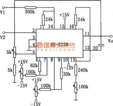
Division Circuit 4(XR-2228)
Published:2011/7/27 5:38:00 Author:Sue | Keyword: Division Circuit | From:SeekIC

As seen in the figure, the division circuit consists of monolithic multiplier integrated circuit XR-2228. The relation between the output signal V1 and input signal V2 is: Vo=10V1/V2.
The input signal V1 can be either positive or negative but V2 must be negative. If V2 is positive, the circuit will be locked (but it will not broke the integrated package). Every potentiometer is used to adjust the circuit so that it can work at the best working state. At the same time, it can use the known reference voltage to check the circuit.
Reprinted Url Of This Article:
http://www.seekic.com/circuit_diagram/Control_Circuit/Division_Circuit_4XR_2228.html
Print this Page | Comments | Reading(3)

Article Categories
power supply circuit
Amplifier Circuit
Basic Circuit
LED and Light Circuit
Sensor Circuit
Signal Processing
Electrical Equipment Circuit
Control Circuit
Remote Control Circuit
A/D-D/A Converter Circuit
Audio Circuit
Measuring and Test Circuit
Communication Circuit
Computer-Related Circuit
555 Circuit
Automotive Circuit
Repairing Circuit
Code: