Control Circuit
Darkroom Exposure Timer Lamp Circuit
Published:2011/4/22 4:23:00 Author:Christina | Keyword: Darkroom Exposure, Timer Lamp | From:SeekIC

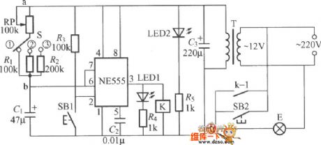
The darkroom exposure timer lamp circuit is as shown, the ne555 time base circuit and the potentiometer rp, capacitor c form the single-stable trigger. Usually the circuit is in reset state, pin-3 of ne555 send out the low-level current, relay K does not operate, exposure light E does not shine. LED led2 is designed as the indicator light, this indicator lightilluminates the dial of potentiometer rp. At this point the internal discharge of ne555 is conducted, capacitor C1 is shorted and can not be charged. k can be the small medium-power electromagnetic relay such as jzc-22f and dc12v.
Reprinted Url Of This Article:
http://www.seekic.com/circuit_diagram/Control_Circuit/Darkroom_Exposure_Timer_Lamp_Circuit.html
Print this Page | Comments | Reading(3)

Article Categories
power supply circuit
Amplifier Circuit
Basic Circuit
LED and Light Circuit
Sensor Circuit
Signal Processing
Electrical Equipment Circuit
Control Circuit
Remote Control Circuit
A/D-D/A Converter Circuit
Audio Circuit
Measuring and Test Circuit
Communication Circuit
Computer-Related Circuit
555 Circuit
Automotive Circuit
Repairing Circuit
Code: