Control Circuit
CAR_WIPER_CONTROL
Published:2009/7/3 3:42:00 Author:May | From:SeekIC

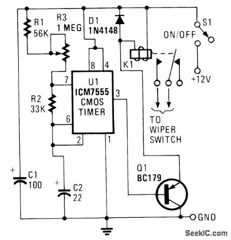
U1 is configured to operate in the standard astable mode, providing a form of relaxation oscillator. When power is applied, C2 initially charges through R1, R2 and R3 to two-thirds of the supply voltage. At that point, U1 senses that its threshold volt-age at pin 6 has been reached, and triggers the timer, causing its output at pin 3 to go high. That high, applied to the base of Q1, keeps the transistor in the off state. Now 02 begins to discharge through R2 to pin 7 of U1. When C2 has discharged to about one-third of the supply voltage, U1 is toggled back to its original state. C2 starts to charge again, as pin 3 of U1 goes low. The low at pin 3 causes Q1-which serves as an emitter-follower buffer stage-to turn on, allowing current to flow through the coil of relay K1. That, in turn, causes K1's contacts to close, applying power to the wipers. The charge time of capacitor C2 is determined by the setting of potentiometer R3. Capacitor C2 should be a tantalum type, and actually, almost any 12-volt coil relay with sufficiently heavy contacts should serve well.
Reprinted Url Of This Article:
http://www.seekic.com/circuit_diagram/Control_Circuit/CAR_WIPER_CONTROL.html
Print this Page | Comments | Reading(3)

Article Categories
power supply circuit
Amplifier Circuit
Basic Circuit
LED and Light Circuit
Sensor Circuit
Signal Processing
Electrical Equipment Circuit
Control Circuit
Remote Control Circuit
A/D-D/A Converter Circuit
Audio Circuit
Measuring and Test Circuit
Communication Circuit
Computer-Related Circuit
555 Circuit
Automotive Circuit
Repairing Circuit
Code: