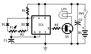
Control Circuit
Brightness Control for small Lamp
Published:2013/7/23 21:12:00 Author:muriel | Keyword: Brightness Control, small Lamp | From:SeekIC

Parts:P1 470K Linear PotentiometerR1 10K 1/4W ResistorR2 47K 1/4W Resistor (See Notes)R3 1K5 1/4W ResistorC1 22nF 63V Polyester CapacitorC2 100µF 25V Electrolytic CapacitorD1,D2 1N4148 75V 150mA DiodesIC1 7555 or TS555CN CMos Timer ICQ1 BD681 100V 4A NPN Darlington TransistorLP1 1.5V 200mA Bulb (See Notes)SW1 SPST SwitchB1 3V (Two 1.5V AA or AAA cells in series, etc.)
Circuit operation:This device was designed on request, to control the light intensity of four filament lamps (i.e. a ring illuminator) for close-up pictures with a digital camera, powered by two AA or AAA batteries. Obviously it can be used in other ways, at anyone's will.IC1 generates a 150Hz squarewave having a variable duty-cycle. When the cursor of P1 is fully rotated towards D1, the output positive pulses appearing at pin 3 of IC1 are very narrow. Lamp LP1, driven by Q1, is off as the voltage across its leads is too low. When the cursor of P1 is rotated towards R2, the output pulses increase in width, reaching their maximum amplitude when the potentiometer is rotated fully clockwise. In this way the lamp reaches its full brightness.
Notes:LP1 could be one or more 1.5V bulbs wired in parallel. Maximum total output current allowed is about 1A.R2 limits the output voltage, measured across LP1 leads, to 1.5V. Its actual value is dependent on the total current drawn by the bulb(s) and should be set at full load in order to obtain about 1.5V across the bulb(s) leads when P1 is rotated fully clockwise.
Reprinted Url Of This Article:
http://www.seekic.com/circuit_diagram/Control_Circuit/Brightness_Control_for_small_Lamp.html
Print this Page | Comments | Reading(3)

Article Categories
power supply circuit
Amplifier Circuit
Basic Circuit
LED and Light Circuit
Sensor Circuit
Signal Processing
Electrical Equipment Circuit
Control Circuit
Remote Control Circuit
A/D-D/A Converter Circuit
Audio Circuit
Measuring and Test Circuit
Communication Circuit
Computer-Related Circuit
555 Circuit
Automotive Circuit
Repairing Circuit
Code: