Control Circuit
Boiling Water Alarm (1)
Published:2011/6/27 3:20:00 Author:Sue | Keyword: Boiling Water, Alarm | From:SeekIC

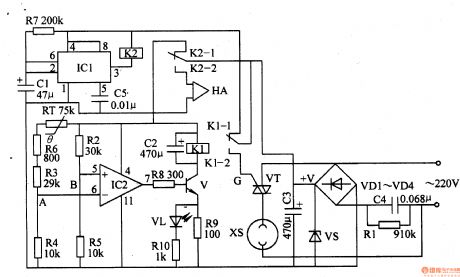
When the power is on, +V voltage will be put on IC2's pin 4, and will provide IC2 with working power. Then IC2's pin 5 has a higher voltage than pin 6. IC's pin 7 will output high level which will make V connected. VL is illuminated. K1 will work and make K1-2 connected. VT is triggered to connected and the electric kettle will begin to work.
As the temperature is going up, RT's resistance value is going down. When the temperature reaches 100℃, IC2's pin 6 has a higher voltage than pin 5 and pin 7 will output low level which will make V disconnected. VT is disconnected and the kettle stops working. When V is disconnected, VL is off.
When C1 finishes charging, IC1's pin 2 turns to high level and pin 3 outputs low level. K2-2 is connected and HA makes an alarm sound to indicate that the water is boiling.
Reprinted Url Of This Article:
http://www.seekic.com/circuit_diagram/Control_Circuit/Boiling_Water_Alarm_1.html
Print this Page | Comments | Reading(3)

Article Categories
power supply circuit
Amplifier Circuit
Basic Circuit
LED and Light Circuit
Sensor Circuit
Signal Processing
Electrical Equipment Circuit
Control Circuit
Remote Control Circuit
A/D-D/A Converter Circuit
Audio Circuit
Measuring and Test Circuit
Communication Circuit
Computer-Related Circuit
555 Circuit
Automotive Circuit
Repairing Circuit
Code: