Control Circuit
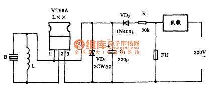
Blown fuse alarm circuit diagram
Published:2014/3/20 20:44:00 Author:lynne | Keyword: Blown fuse alarm circuit diagram, VT66A, 2CW52 | From:SeekIC

With this alarm can quickly determine if the fuse blows .WorksFuse alarm circuit as shown. When the fuse Fu intact , Fu ends of the same potential , C1 voltage at both ends of days , the alarm does not work. When Fu blown fuse , 220V AC by the load ( ie, appliances ) input current limit by the Rl buck , VD2 rectifier , C1 filtering and VD1 regulated output DC voltage of about 3V . This DC voltage supply music IC VT66A work on piezoelectric ceramics B loud electronic music newspaper tube sound, alerting the master fuse has blown .Component selection and productionMusic IC available VT66A Music transistor should be used in L-shaped , with each song name within the reservoir favorite may be. VD1 with 2cw52 regulator diode , VD2 1N4004 type silicon rectifier diodes are available .R1 with RJ-1W metal film resistors. C1 with CD11-10v electrolytic capacitor . L color code available 2.5mH inductor . B with FT-27, HTD27A-1 type and other piezoelectric ceramics .Entire alarm lines can be installed in a small plastic box , leads to two wires , it will be parallel to the ends of the fuse Fu .As shown in Figure blown fuse alarm circuit diagram:
Reprinted Url Of This Article:
http://www.seekic.com/circuit_diagram/Control_Circuit/Blown_fuse_alarm_circuit_diagram.html
Print this Page | Comments | Reading(3)

Article Categories
power supply circuit
Amplifier Circuit
Basic Circuit
LED and Light Circuit
Sensor Circuit
Signal Processing
Electrical Equipment Circuit
Control Circuit
Remote Control Circuit
A/D-D/A Converter Circuit
Audio Circuit
Measuring and Test Circuit
Communication Circuit
Computer-Related Circuit
555 Circuit
Automotive Circuit
Repairing Circuit
Code: