Control Circuit
Basic_triac_switches
Published:2009/7/21 22:03:00 Author:Jessie | From:SeekIC

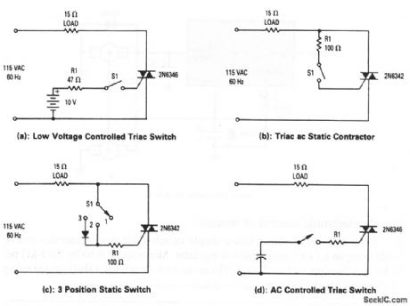
These circuits show triacs that are used to control a pure resistive load (of about 7 A) across an ac line. In Fig. 8-5A, gate current is supplied to the triac from the 10-V battery when S1 is closed. The triac tums on and remains on until S1 is opened. This cirquit switches at zero current, except for initial turn on, so S1 can be a very low-current switch (carring only triac gate current). The triac switch of Fig.8-5B has the same characteristics as Fig. 8-5A, except that the battery is eliminated. In the circuit of Fig. 8-5C, when S1 is in position 1, the triac receives no gate current and is nonconducting. With S1 in position 2, operation is the same as in Fig. 8-5B. With S1 in position 3, the triac receives gate current only on positive half-cycles, and power to the load is half-wave. Figure 8-5D shows ac control of the triac.
Reprinted Url Of This Article:
http://www.seekic.com/circuit_diagram/Control_Circuit/Basic_triac_switches.html
Print this Page | Comments | Reading(3)

Article Categories
power supply circuit
Amplifier Circuit
Basic Circuit
LED and Light Circuit
Sensor Circuit
Signal Processing
Electrical Equipment Circuit
Control Circuit
Remote Control Circuit
A/D-D/A Converter Circuit
Audio Circuit
Measuring and Test Circuit
Communication Circuit
Computer-Related Circuit
555 Circuit
Automotive Circuit
Repairing Circuit
Code: