Control Circuit
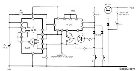
BLIP_AND_HOLD_RADIO_CONTROL
Published:2009/7/20 1:50:00 Author:Jessie | From:SeekIC

Coder uses two ICs to generate sequence of pulses suitable for actuators of radio control system. During standby, oscillator formed by NAND gate 1 operates at 0.5 Hz as determined by C1 and R1, and all four outputs of 7490 IC are zero. When switch AL is closed, 7490 is clocked by negative edge of oscillator waveform and Tr1 becomes forward-biased. Output of NAND gate 2 then drops to zero, stopping oscillator and holding outputs of 7490. When switch A is opened, outputs of 7490 again drop to zero. Many different blip-and-hold combinations can be obtained by suitable arrangement of switches and gates.-G. D. Southern, Sequence Generator for Radio Control, Wireless World, Jan. 1976, p 60.
Reprinted Url Of This Article:
http://www.seekic.com/circuit_diagram/Control_Circuit/BLIP_AND_HOLD_RADIO_CONTROL.html
Print this Page | Comments | Reading(3)

Article Categories
power supply circuit
Amplifier Circuit
Basic Circuit
LED and Light Circuit
Sensor Circuit
Signal Processing
Electrical Equipment Circuit
Control Circuit
Remote Control Circuit
A/D-D/A Converter Circuit
Audio Circuit
Measuring and Test Circuit
Communication Circuit
Computer-Related Circuit
555 Circuit
Automotive Circuit
Repairing Circuit
Code: