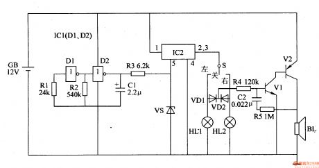
Control Circuit
Automobile Steering Flasher (4)
Published:2011/6/30 5:50:00 Author:Sue | Keyword: Automobile, Steering, Flasher | From:SeekIC

The low-frequency oscillator will generate 1Hz pulse signals which will control HL1 and HL2.
IC2's inner switch will be connected intermittently under the control of the signals. When the pulse signals are positive, IC2's inner switch will be connected. When the signals are negative, IC's inner switch will be disconnected.
When S is put on LEFT , the left turn lamp HL1 will be illuminated and VD1 will be connected intermittently. The indicator will begin to work and BL will make a warning tone. When S is put on RIGHT , the right trun lamp HL2 will be illuminated and VD2 is connected intermittently. The indicator will begin to work. When S is put in middle, HL1 and HL2 are both off and VD1,VD2 are both disconnected. The indicator doesn't work and BL makes no sound.
Reprinted Url Of This Article:
http://www.seekic.com/circuit_diagram/Control_Circuit/Automobile_Steering_Flasher_4.html
Print this Page | Comments | Reading(3)

Article Categories
power supply circuit
Amplifier Circuit
Basic Circuit
LED and Light Circuit
Sensor Circuit
Signal Processing
Electrical Equipment Circuit
Control Circuit
Remote Control Circuit
A/D-D/A Converter Circuit
Audio Circuit
Measuring and Test Circuit
Communication Circuit
Computer-Related Circuit
555 Circuit
Automotive Circuit
Repairing Circuit
Code: