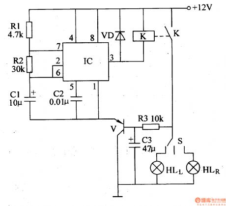
Control Circuit
Automobile Steering Flasher (3)
Published:2011/6/30 5:42:00 Author:Sue | Keyword: Automobile, Steering, Flasher | From:SeekIC

When S is disconnected, V is disconnected. IC's pin 1 and pin 3 will output high level while the oscillator doesn't work. When S is connected, V is connected. IC's pin 1 will output low level. The oscillator begins to work. IC's pin 3 will output oscillate signals which will make K connected and disconnected intermittently. HLL or HLR will be illuminated simultaneously. When S is put in the middle, V is disconnected. The oscillator will stop working. The turn lamps will be off.
Reprinted Url Of This Article:
http://www.seekic.com/circuit_diagram/Control_Circuit/Automobile_Steering_Flasher_3.html
Print this Page | Comments | Reading(3)

Article Categories
power supply circuit
Amplifier Circuit
Basic Circuit
LED and Light Circuit
Sensor Circuit
Signal Processing
Electrical Equipment Circuit
Control Circuit
Remote Control Circuit
A/D-D/A Converter Circuit
Audio Circuit
Measuring and Test Circuit
Communication Circuit
Computer-Related Circuit
555 Circuit
Automotive Circuit
Repairing Circuit
Code: