Control Circuit
Automobile Steering Flasher (1)
Published:2011/6/30 5:29:00 Author:Sue | Keyword: Automobile, Steering, Flasher | From:SeekIC

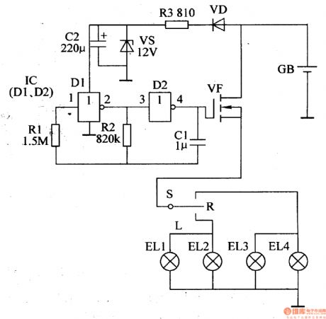
S is the steering switch, and EL1 is left frontturn lamp, EL2 is left rear turn lamp, EL3 is right front turn lamp while EL4 is right rear turn lamp. GB is the storage battery of the automobile.
GB will provide VF with working voltage. The other circuit will provide IC with +12V voltage after limitation, stablization and filtration.
After the multivibrator begins to work, IC's pin 4 will output low-frequency square wave pulse signals. When S is connected, VF will be connected and disconnected intermittently. Then EL1,EL2,EL3,EL4 will start to twinkle. When VF is connected, the turn lamps will be illuminated. When VF is disconnected, the turn lamps will be off.
Reprinted Url Of This Article:
http://www.seekic.com/circuit_diagram/Control_Circuit/Automobile_Steering_Flasher_1.html
Print this Page | Comments | Reading(3)

Article Categories
power supply circuit
Amplifier Circuit
Basic Circuit
LED and Light Circuit
Sensor Circuit
Signal Processing
Electrical Equipment Circuit
Control Circuit
Remote Control Circuit
A/D-D/A Converter Circuit
Audio Circuit
Measuring and Test Circuit
Communication Circuit
Computer-Related Circuit
555 Circuit
Automotive Circuit
Repairing Circuit
Code: