Control Circuit
Automatic reversing circuit of the phase-electromotor with the inching switch
Published:2011/9/2 2:28:00 Author:Christina | Keyword: Automatic reversing circuit, phase-electromotor, inching switch | From:SeekIC
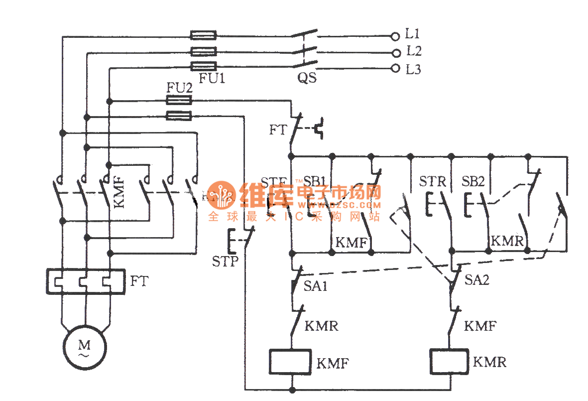
As the figure shows, the SA1 and SA2 are the position limit switches; the SB1 and SB2 are the inching switch. Set the SB1 as an example, it is a composite switch, you can start the KMF by pressing it, the electromotor operates positively, if you unclasp the finger, the KMF will loss power, so the electromotor is in the inching state. After you press the STF, the normally closed contact point of SB1 is in the closed state, so the KMF can protect itself, the electromotor can operate long-standing. Set the SA1 as an example, in the normal operation condition, after the mechanical hits the inching switch SA1, the normally closed contact point cuts off to cut off the KMF return circuit, the electromotor stops.
Reprinted Url Of This Article:
http://www.seekic.com/circuit_diagram/Control_Circuit/Automatic_reversing_circuit_of_the_phase_electromotor_with_the_inching_switch.html
Print this Page | Comments | Reading(3)

Article Categories
power supply circuit
Amplifier Circuit
Basic Circuit
LED and Light Circuit
Sensor Circuit
Signal Processing
Electrical Equipment Circuit
Control Circuit
Remote Control Circuit
A/D-D/A Converter Circuit
Audio Circuit
Measuring and Test Circuit
Communication Circuit
Computer-Related Circuit
555 Circuit
Automotive Circuit
Repairing Circuit
Code: