Alarm Control
consisting of TWH8751 lock control anti-theft alarm circuit
Published:2011/7/8 3:20:00 Author:Fiona | Keyword: lock control anti-theft alarm | From:SeekIC
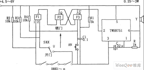
Figure shows the lock control anti-theft alarm circuit. The circuit consists of RS flip-flop, gated oscillator, the alarm circuit and so on.RS flip-flop consists of the NAND gate F2, F3, strobe oscillator consists of integrated circuits TWH8751 and R, C.
When the SKK is in the lock position, and the input 2 of NAND gate F1 is high, the state of DBK1-n is direct reflected by F1, if DBK1-n has an open circuit, the F1 output is low, RS flip-flop is set to 1 ,Choose the end (2) feet of the corresponding TWH8751 is low, trigger oscillator starts to oscillate, the oscillation signal makes the loudspeaker alarm.
Reprinted Url Of This Article:
http://www.seekic.com/circuit_diagram/Control_Circuit/Alarm_Control/consisting_of_TWH8751_lock_control_anti_theft_alarm_circuit.html
Print this Page | Comments | Reading(3)

Article Categories
power supply circuit
Amplifier Circuit
Basic Circuit
LED and Light Circuit
Sensor Circuit
Signal Processing
Electrical Equipment Circuit
Control Circuit
Remote Control Circuit
A/D-D/A Converter Circuit
Audio Circuit
Measuring and Test Circuit
Communication Circuit
Computer-Related Circuit
555 Circuit
Automotive Circuit
Repairing Circuit
Code: