Alarm Control
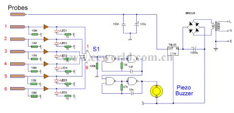
The water height alarm circuit diagram
Published:2012/8/6 4:23:00 Author:Ecco | Keyword: water height , alarm | From:SeekIC

This circuit will trigger with any fluid with a resistance under 900K between the maximum separation distance of the probes. Let me explain further. The circuit uses a 4050B CMOS hex buffer working on a 5 volt supply. All gates are biased off by the 10M resistors connected between ground and buffer input. The common probe the topmost probe above probe 1 in the diagram above is connected to the positive 5 volt supply. If probe 1 is spaced 1 cm away from the common probe and tap water at 25 ?C is detected between the probes (a resistance of 20k) then the top gate is activated and the LED 1 will light. Similarly if probe 2 at 2 cm distance from the common probe detects water, LED 2 will light and so on. Switch 1 is used to select which output from the hex buffer will trigger the audible oscillator made from the gates of a CMOS 4011B IC.Placement of Probes:As 7 wires are needed for the probe I reccommend the use of 8 way computer ribbon cable. The first two wires may be doubled and act as the common probe wire. Each subsequent wire may be cut to required length, if required a couple of millimetres of insulation may be stripped back, though the open cut off wire end should be sufficient to act as the probe. The fluid and distance between probe 6 and the common probe wire must be less than 900k. This is because any voltage below 0.5 Volt is detected by the CMOS IC as logic 0. A quick potential check using a 900k resistance and the divider formed with the 10M resistor at the input proves this point: 5 x (0.9 / (0.9+10) = 0.41 Volt.
Reprinted Url Of This Article:
http://www.seekic.com/circuit_diagram/Control_Circuit/Alarm_Control/The_water_height_alarm_circuit_diagram.html
Print this Page | Comments | Reading(3)

Article Categories
power supply circuit
Amplifier Circuit
Basic Circuit
LED and Light Circuit
Sensor Circuit
Signal Processing
Electrical Equipment Circuit
Control Circuit
Remote Control Circuit
A/D-D/A Converter Circuit
Audio Circuit
Measuring and Test Circuit
Communication Circuit
Computer-Related Circuit
555 Circuit
Automotive Circuit
Repairing Circuit
Code: