Alarm Control
SECURITY_DOOR_AJAR_ALARM
Published:2009/7/7 7:27:00 Author:May | From:SeekIC

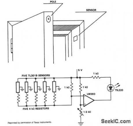
In operation, the TL3019 device will activate, or become low, when a south pole of a magnet comes near the chip face of the device. The example shows five doors. Each door has a magnet embedded in its edge with the south pole facing the outer surface. At the point where the magnet is positioned with the door closed, a TL3019 sensor is placed in the door jamb. With the door closed, the Hall devices will be in a logic low state. This design has five doors and uses five TL3019 devices. Each TL3019 has a 4-KΩ resistor in series and all door sensor and resistor sets are in parallel and connected to the inverting input of an LM393 comparator. With all doors closed, the effective resistance will be about 800 0 and produce 2.2 V at the inverting input. The noninverting input goes to a voltage divider network which sets the reference voltage. The 1.5-KΩ potentiometer is adjusted so the indicator goes out with all doors closed. This will cause 2.35 V to appear at the noninverting input of the comparator. When a door opens, the voltage at the inverting input will go to 2.5 V which is greater than VREF, and the LED will light. A large number of doors and windows can be monitored with this type of circuit. Also, it could be expanded to add an audible alarm in addition to the visual LED.
Reprinted Url Of This Article:
http://www.seekic.com/circuit_diagram/Control_Circuit/Alarm_Control/SECURITY_DOOR_AJAR_ALARM.html
Print this Page | Comments | Reading(3)

Article Categories
power supply circuit
Amplifier Circuit
Basic Circuit
LED and Light Circuit
Sensor Circuit
Signal Processing
Electrical Equipment Circuit
Control Circuit
Remote Control Circuit
A/D-D/A Converter Circuit
Audio Circuit
Measuring and Test Circuit
Communication Circuit
Computer-Related Circuit
555 Circuit
Automotive Circuit
Repairing Circuit
Code: