Alarm Control
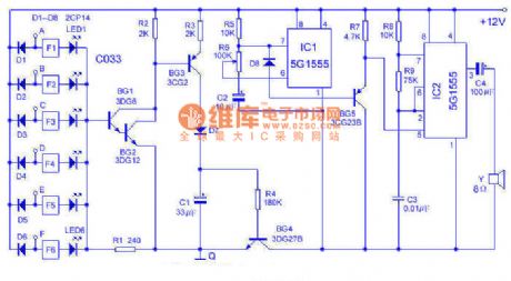
Multi-channel burglar alarm circuit diagram
Published:2014/1/19 21:46:00 Author:lynne | Keyword: Multi-channel burglar alarm circuit diagram, | From:SeekIC

This alarm can be 6-way, from 0 to 30 km on the touch line in both sound and lighting for monitoring. Works in the following figure:Using 6 inverter C033 and light-emitting diodes (leds) as a touch alarm display. When the body contact (directly and/or wear gloves and indirect touch) when any one end in A ~ F, the end brings low potential, the inverter makes light-emitting tube LED display. At this moment, BG1 ~ BG4 conduction, C1 charging, acoustics part (IC1, IC2, etc.) begin to work. IC1, produce about 1 hz sawtooth wave by BG5 buffer to add to the IC2 modulation, IC1 oscillation frequency from low to high, the speaker sends out the similar public security police car alarm.
Use installation should pay attention to the Q end reliable to use A wire from the earth, A ~ F side respectively with bare copper wire to the surveillance, fixed place need porcelain insulation, at the same time pay attention to the rain, water, etc. Between cause and to form A low impedance. The alarm sensitivity is extremely high, standing on a chair touch wires can also call the police, the human body to leave after the all-clear to delay a few seconds. Power supply adopts 8 batteries. Adjust the R6 can change the tone.
Reprinted Url Of This Article:
http://www.seekic.com/circuit_diagram/Control_Circuit/Alarm_Control/Multi_channel_burglar_alarm_circuit_diagram.html
Print this Page | Comments | Reading(3)

Article Categories
power supply circuit
Amplifier Circuit
Basic Circuit
LED and Light Circuit
Sensor Circuit
Signal Processing
Electrical Equipment Circuit
Control Circuit
Remote Control Circuit
A/D-D/A Converter Circuit
Audio Circuit
Measuring and Test Circuit
Communication Circuit
Computer-Related Circuit
555 Circuit
Automotive Circuit
Repairing Circuit
Code: